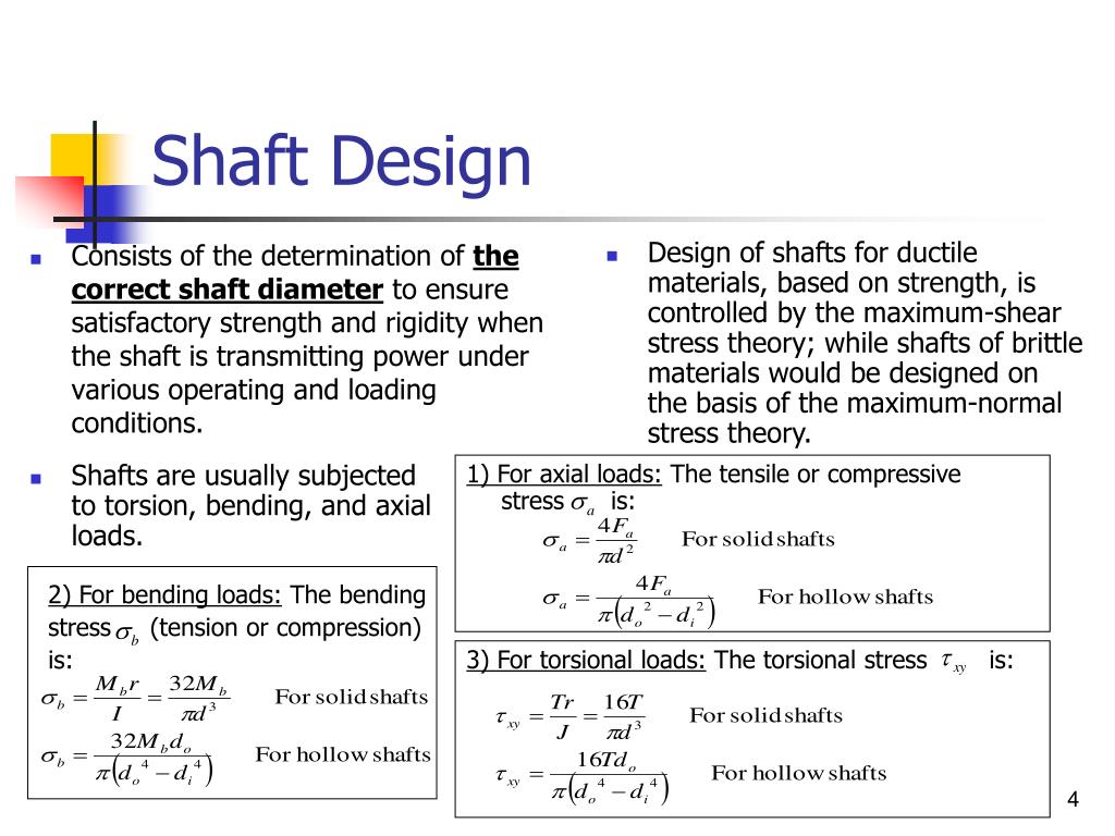
Design of Shaft 18 Shaft design based on strength A i l stress Axial t continue. Stress due to torsion.
Ppt Shaft Design Powerpoint Presentation Free Download Id 3955524
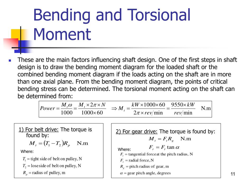
Torque on the shaft Note.
. The rotating shaft is required for closed-tank operation and the type depends on degree of seal required operating pressure and operating temperature. Slope at the bearings and shaft support elements shear deflection due to transverse loading. Compare combined stresses to suitable allowable stresses.
Shear stress due to torsion T. Shaft Design ASME Shaft Equations Design of Shaft for Torsional Rigidity Standard Sizes of Shafts Bending and Torsional Moments. Combined bending and torsion loads on shaft.
DESIGN OF SHAFTS. 7024 9549 hp kW T NRPM NRPM. Design of Unprotected type Flange Coupling The usual proportions for an unprotected type cast iron flange couplings d diameter of the shaft or inner diameter of the hub D Outside diameter of hub D2d Length of hub L 15d Pitch circle diameter of bolts D13d Outside diameter of flange D2 D1 D1 D 2 D1 D 4d Thickness of flange tf 05d Number of.
Shaft Design for Stress Shaft Stresses Figure 621 Page 296 Notch-sensitivity curves for materials in reversed torsion. Loads on shaft due to pulleys Torque and Bending moment diagrams for the pulley system Power toque speed For linear motion. Couplings are classified as 1.
The shaft may be designed on the basis of 1. A projection on a rotating part in machinery designed to make sliding contact with another part while rotating and to impart reciprocal or variable motion to it. Shaft design based on strengthShaft design based on strength Desii id h l i fign is carried out so that stress at any location of the shaft should not exceed material yielding.
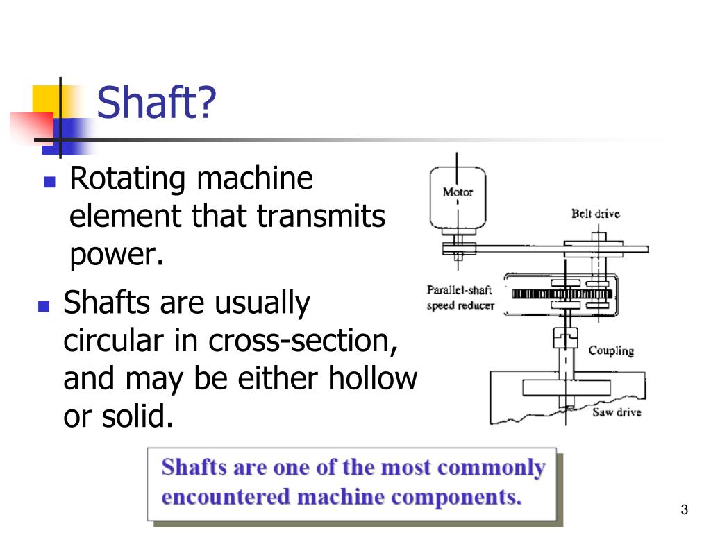
Ppt On Shaft Design Ppt on shaft design stickers decalsartificial fingernailsuv gelmanicure pedicure setnail brushuv lampnail polishView Far more is lever 2000 good for tattoos it s a beautiful day to save lives tattoo is fashion gamma real it used to be fashionable 94 uk it movie tattoo ideas iron sharpens iron tattoo ideas is hidden. View Chapter 7-c- Shaft Designppt from MECHANICAL MM3CMT at Uni. A shaft is a rotating member circular cross-section solid or hollow to transmit power or motion.
For larger notch radii use the values of q shear corresponding to r 016 in 4 mm. Shafts can sometimes be square in cross section. To transmit the power using shaft different members are used such as Gears Pulleys Sprockets.
Surface hardening usually only used when the shaft is being used as a bearing surface. Specify the location of bearings to support the shaft. Shaft Materials Shafts are commonly made from low carbon CD or HR steel such as AISI 10201050 steels.
Power Fv force x velocity For rotational motion Power P Torque x angular velocity T in-lbw radsec in-lbsec T2 p n60 in-lbsecnrpm T2 p n6012550. Cams are used to convert rotary motion into reciprocating motion CAMSHAFT. Ti 1 α λ L r 1 1 5 1 0 0 0 4 4 λ λ 2 s yc α 2 λ 115 π nE n 10 for hinged end.
Procedure for design of a shaft 1. Axels are non rotating member carries no torque and it is used to support rotating wheels. Shafts Axles and Spindles A shaft is a rotating member usually of circular cross-section solid or hollow which transmits power and rotational motion.
An axle though similar in shape to the shaft is a stationary machine element and is used to transmit bending moment only. DESIGN MANUFACTURING OF CAMSHAFT INTRODUCTION CAM. Determine the rotational speed of the shaft.
There is absolutely no requirement of removing the crankshaft from the block and sending it to the workshop when RA Power Solutions is called into help support. A propeller shaft is an assembly of one or more tubular shaft connected by universal constant velocity or flexible joints. Shaft subjected to combined twisting moment and bending moment.
Fatigue properties dont usually benefit much from high alloy content and heat treatment. The shaft for a mixer especially a large one involves significant mechanical design partly because of the myriad of shaft lengths impeller sizes and operating. Shafts subjected to twisting moment only.
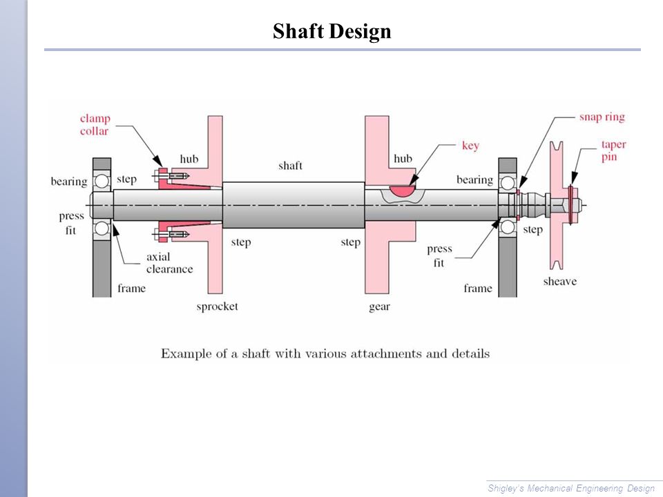
Shaft subjected to bending moment only. 91 9582647131 Tel No. Determine the design of the power-transmitting components or other devices that will be mounted on the shaft and specify the required location of each device.
SHAFT COUPLINGS Shaft couplings are used to connecetwo shafts in such away that when both shafts rotate they act as one unit and transmit power from one shaft to other Shafts to be coupled may have collinear axes intersecting axes or parallel axes at a small distance. Design should consider the following Deflection Bending deflection Torsional deflection. RameshSingh Introduction Torque and Power Transmission Most of rotary prime movers either motors or turbines use shaft to transfer the power Bearings are required for support Shaft failure analysis is critical 2.
Find bending moments from gears pulleys or sprockets that are transmitting loads to or from other devices. Determine torque in shafts from gears pulleys sprockets clutches and couplings. In designing shaft on the basis of strength the following cases may be consider 1.
91-1244378292 4251615 Email ID. Shaft Design Design Manufacture and Project Learning Objectives To understand shaft function types connections. Shigleys Mechanical Engineering Design.
N 225 for fixed end n 16 for ends p partlyy restrained as in bearingg L shaft length syc yyield stress in compression p. Figure 620 Page 295 Notch-sensitivity charts for steels and UNS A92024-T wrought aluminum. The number of tubular pieces and the joints depends on the distance between the gearbox and the axle.
Tr T 16 τShearstressduetotorsion xy 341 o J dc τ π xy. A shaft with one or more cams attached to it eg. Determine the design of the power-transmitting components or other devices that will be mounted on the shaft and specify the required location of each device.
Design of Shafts 1. 2determine the power or the torque to be transmitted by the shaft. Shaft Design Objectives Compute forces acting on shafts from gears pulleys and sprockets.
Section VI Shaft Design Shaft. 1 August 15 2007 1 17. Shaft is a rotating member and it provides axis of rotation for gears pulley flywheels cranks sprockets.
Determine the power or the torque to be transmitted by the shaft.

Topics Introduction Shaft Design Stresses And Loads On Shafts Ppt Video Online Download
Ppt Shaft Design Powerpoint Presentation Free Download Id 3955524
Ppt Shaft Design Powerpoint Presentation Free Download Id 3955524
![]()
Shafts And Shaft Components Ppt Download
![]()
Shafts And Shaft Components Ppt Download
Shafts And Shaft Components Ppt Download
Ppt Shaft Design Powerpoint Presentation Free Download Id 3955524

Unit 2 Design Of Shaft
0 comments
Post a Comment